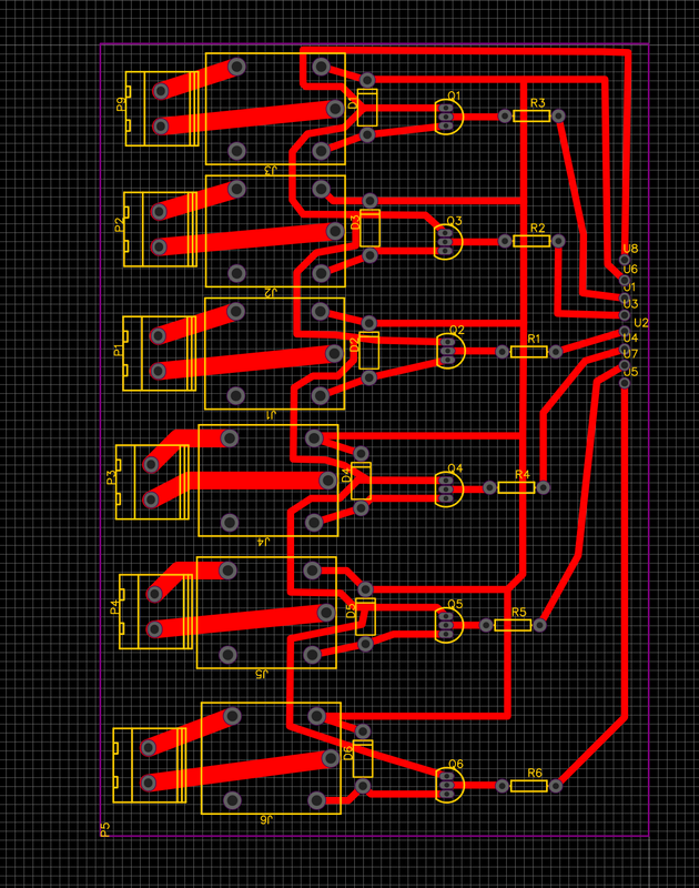
For some time I have wanted to make a light controller that will sync my Christmas lights to songs. I started off by looking at what other people had made. I found this website talking about how they made their own relay board and that is where I am going to start. I started by making the board design which I will cut out later on my CNC router.
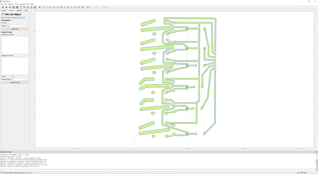
With the design done, I had to make it into gcode that my CNC router can use to cut the board out. For this I used flatcam. I used this video to set up flatcam to make the gcode.
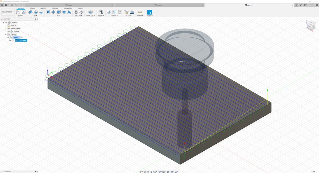
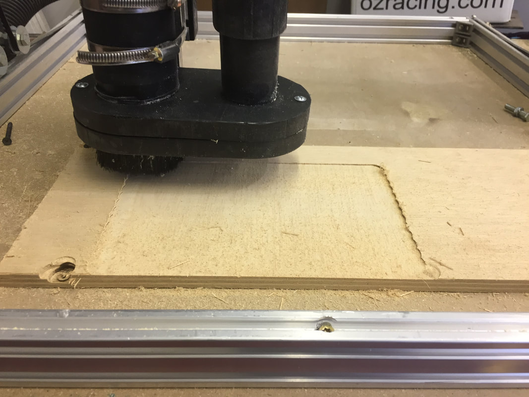
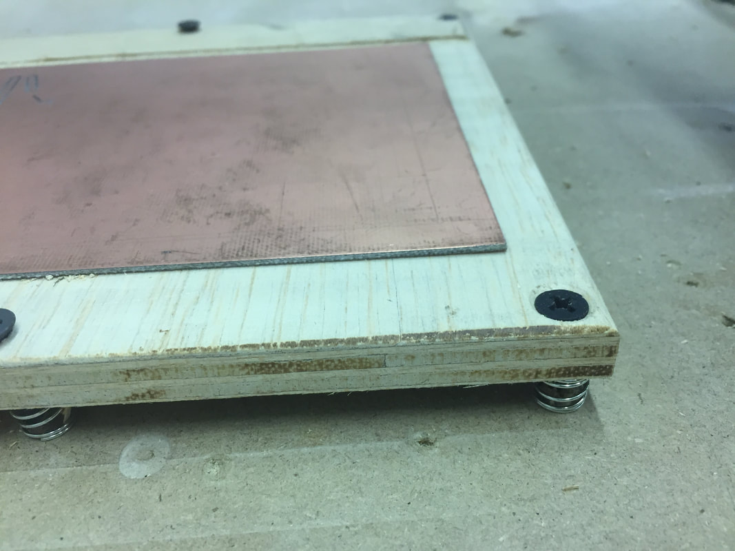
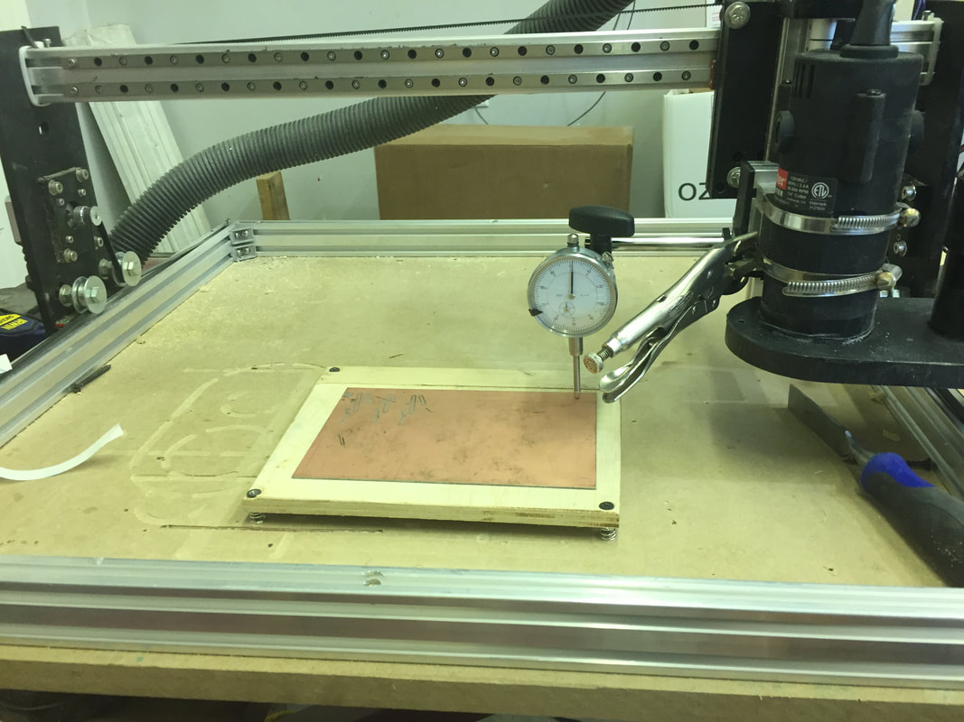
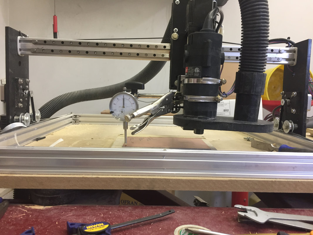
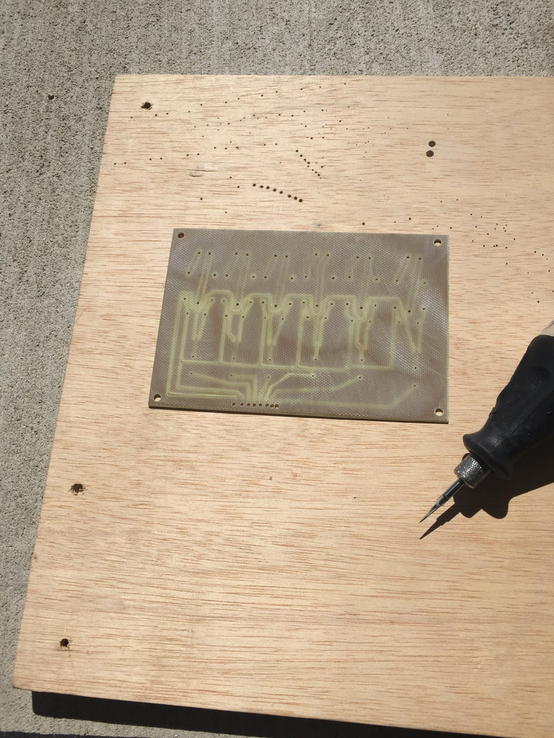
When I went to mill the board, I found a problem. My router's bed was not level so some places it would cut too deep. To fix this, I took a piece of wood and faced it to make is flat. Then I put it on springs so that I could level it.
|
|
|
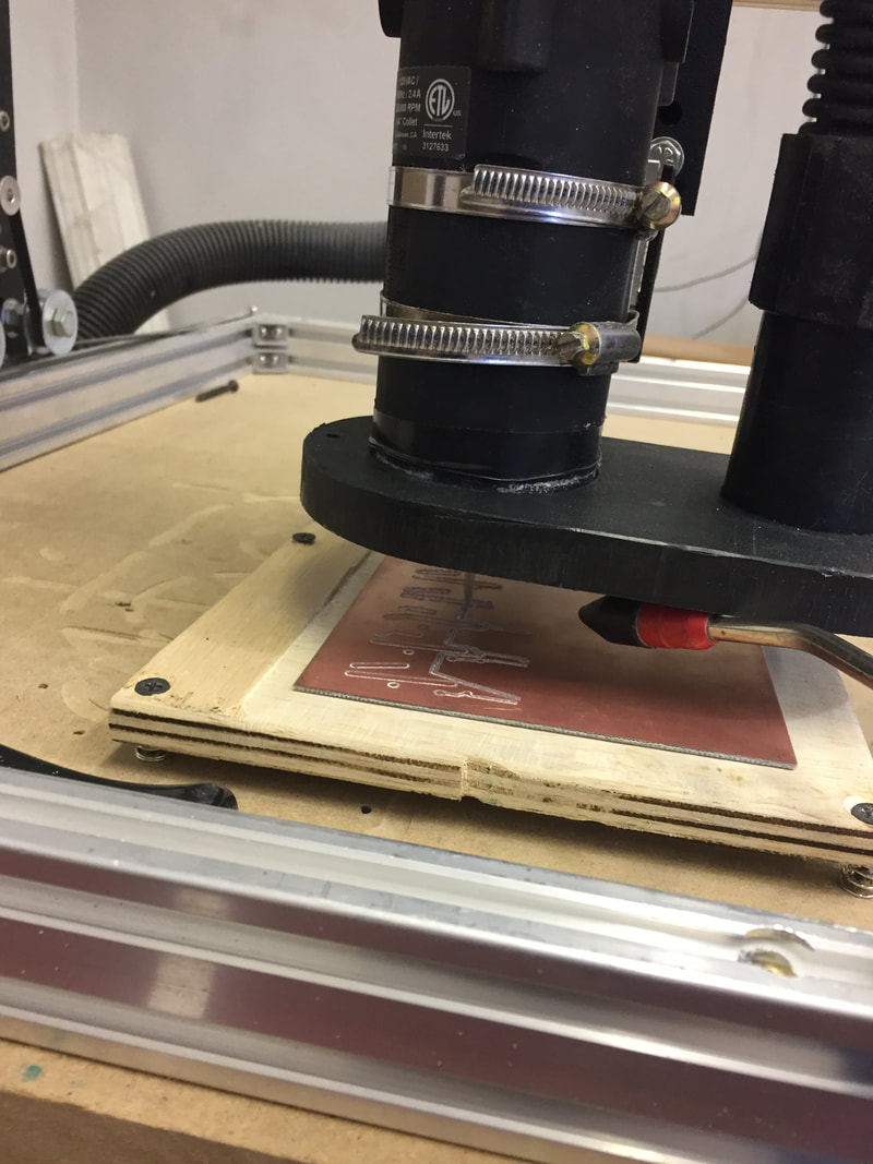
With my new cutting plate, I went and leveled it by turning the screws. Then I cut the two boards on it.
|
|
|
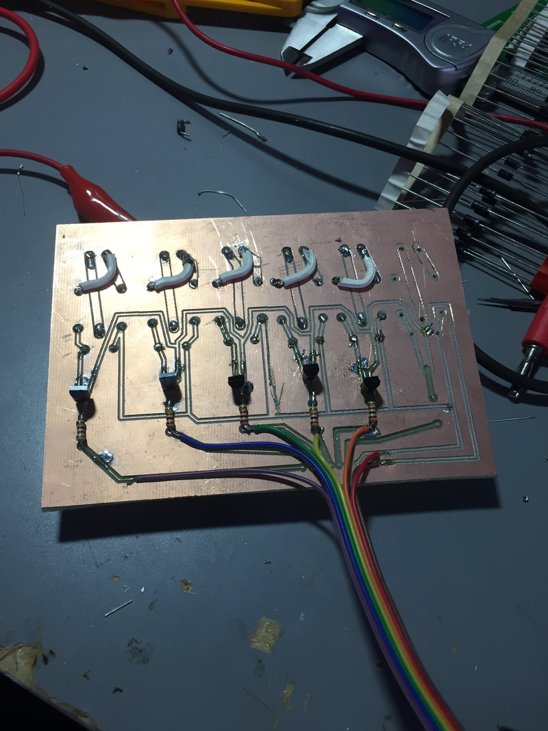
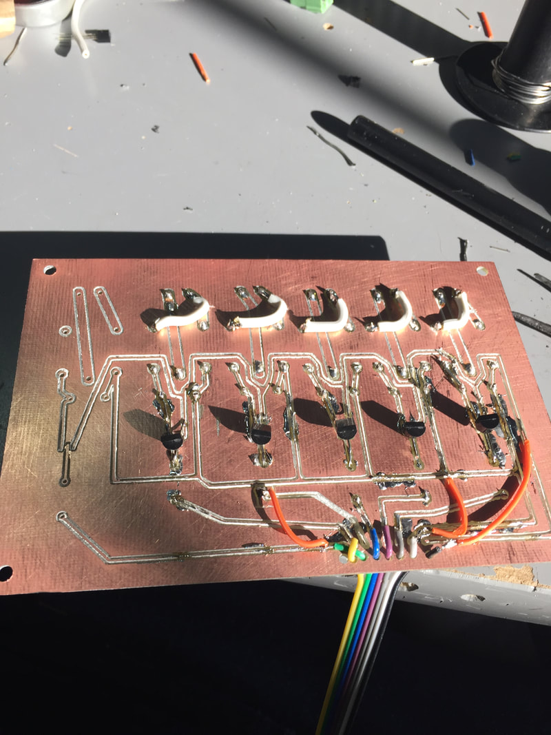
Once the cutting was done I has to drill the holes for the parts to go through.
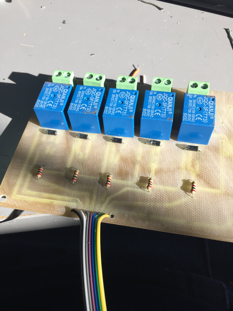
After that I had to solder the parts to my boards. This took a long time as I had to fix some spots that the bit did not cut. After about 4 hours, I had 2 working boards.
|
|
|
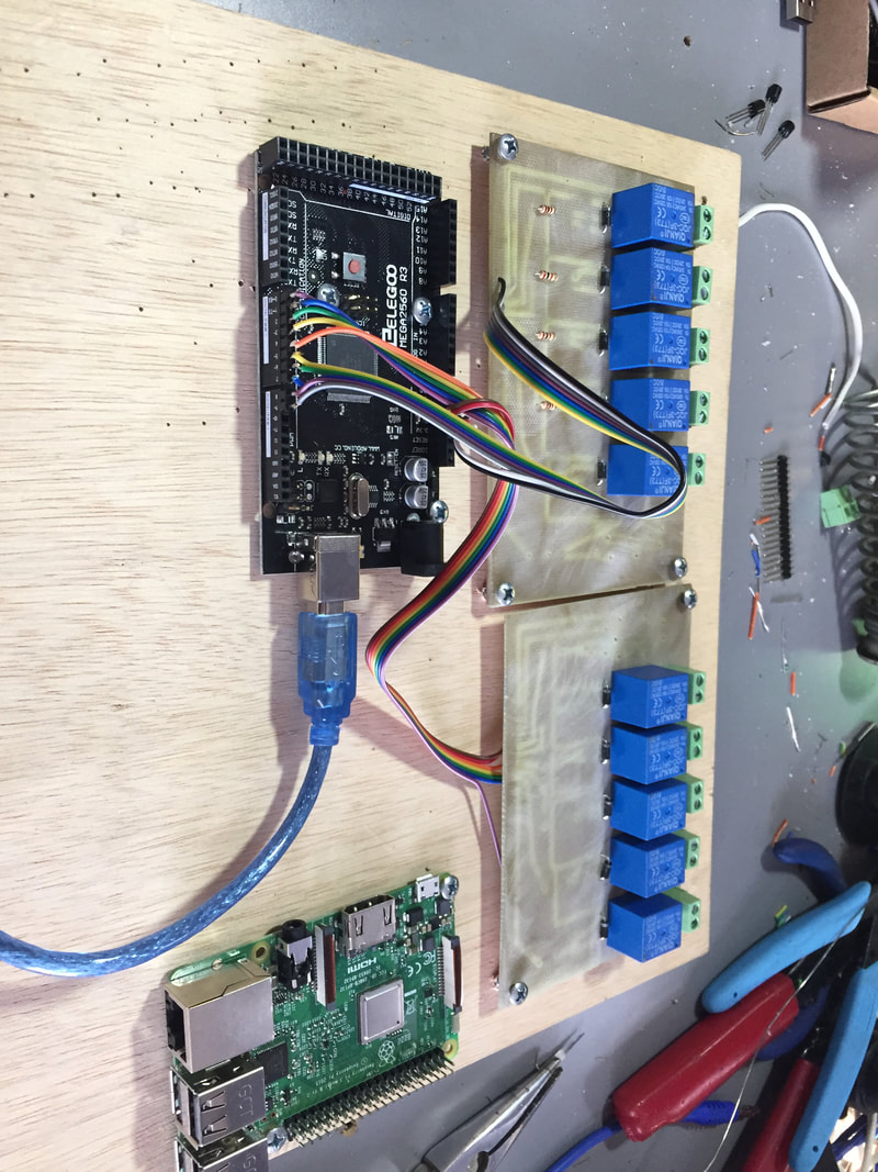
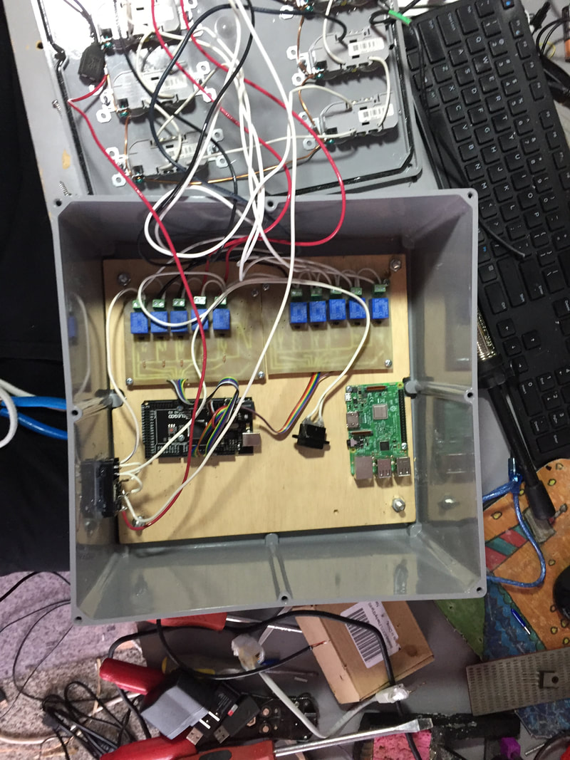
Next I drilled holes in the board and screwed them down to a piece of plywood then connected them to an arduino.
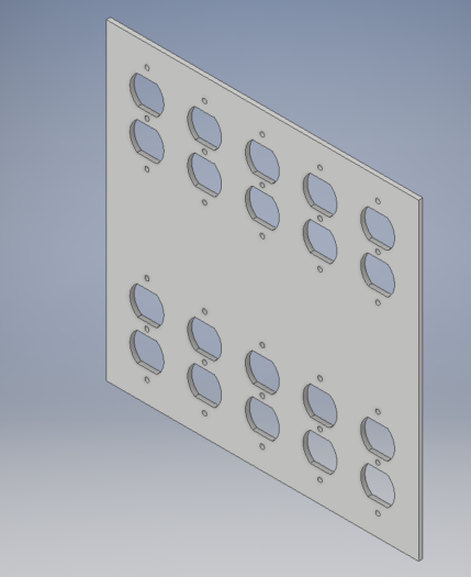
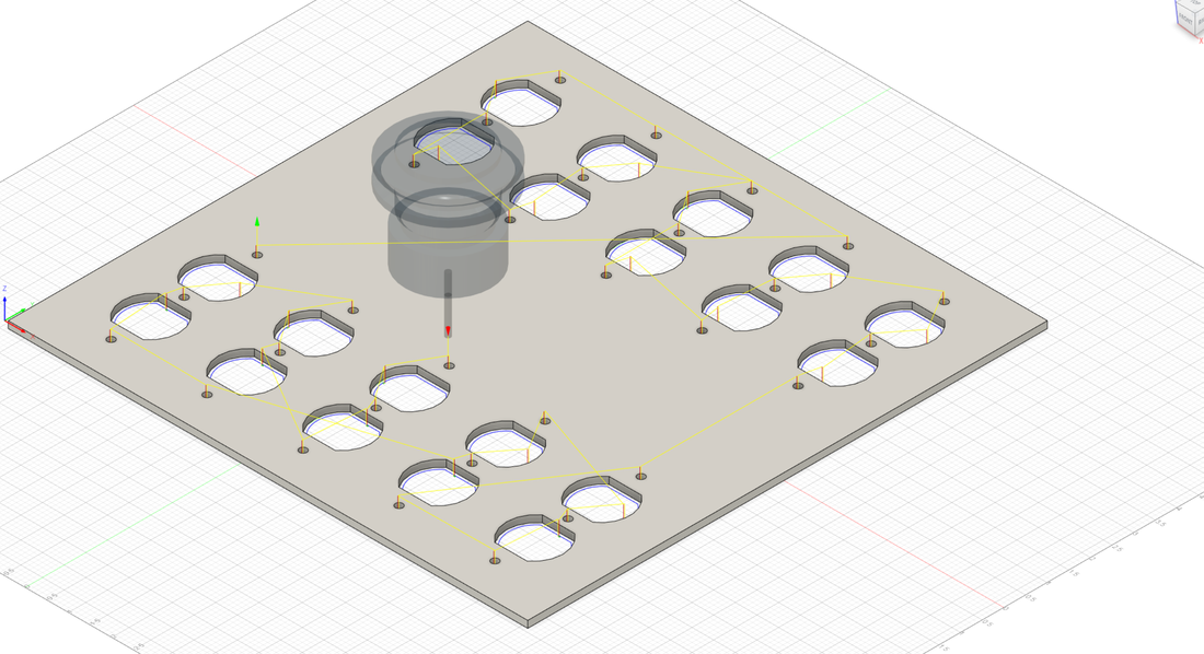
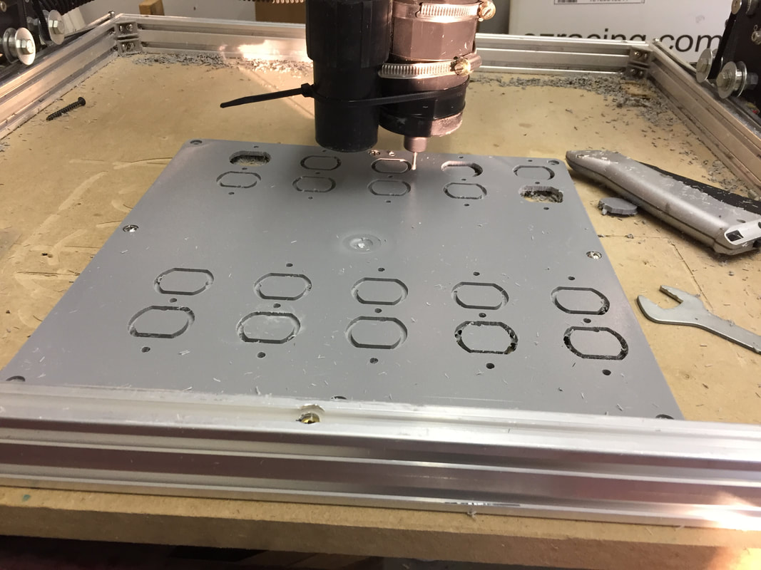
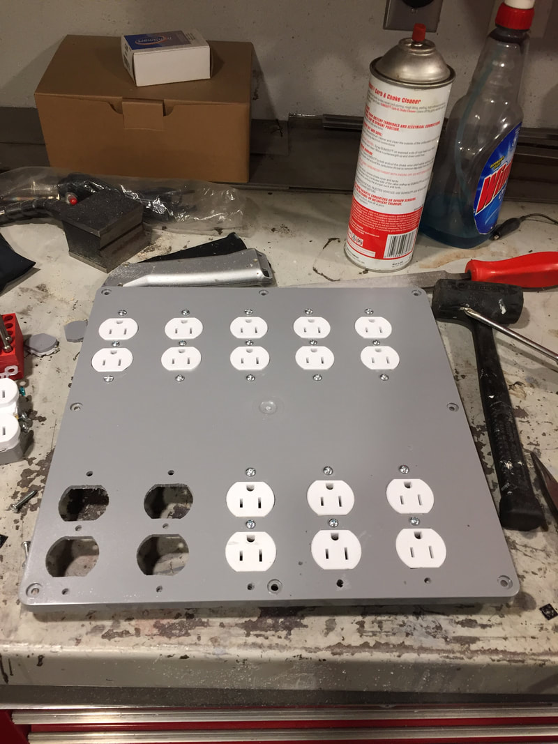
Next I cut the lid of a box to hold 10 outlets so I can connect the lights to them. I drew up the front of the outlets in CAD then turned them into gcode using fusion360.
|
|
|
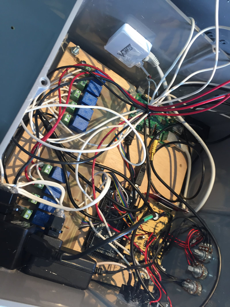
After that I put the outlets in and started wiring (it got out of hand fast).
|
|
|
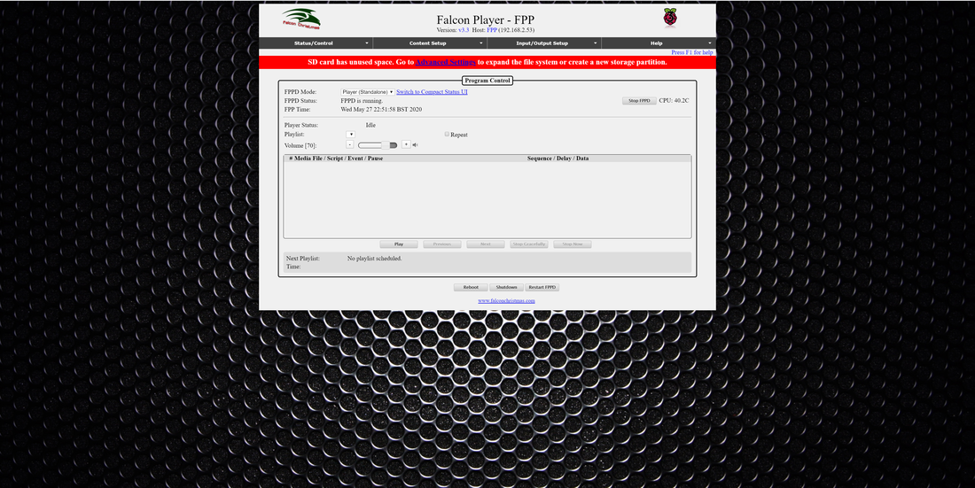
Now onto software. I used a program called Falcon Pi Player. It runs on a raspberry pi and makes a web server that I can control on my computer. I will not go in to detail on how to set it up as there are a lot of tutorials on it. Here is an example.
The arduino's code is simple. It listens for data from the serial port, then when it gets the data it controls the pins of the arduino.
#define CHANNEL_01 2
#define CHANNEL_02 3
#define CHANNEL_03 4
#define CHANNEL_04 5
#define CHANNEL_05 6
#define CHANNEL_06 7
#define CHANNEL_07 8
#define CHANNEL_08 9
#define CHANNEL_09 10
#define CHANNEL_010 11
#define CHANNEL_COUNT 10
int channels[] =
{
CHANNEL_01, CHANNEL_02, CHANNEL_03, CHANNEL_04, CHANNEL_05, CHANNEL_06, CHANNEL_07, CHANNEL_08, CHANNEL_09, CHANNEL_10,
};
int incomingByte[10];
#define BAUD_RATE 57600
void setup()
{
// Begin serial communication
Serial.begin(BAUD_RATE);
// Set up each channel as an output
for(int i = 0; i < CHANNEL_COUNT; i++)
{
pinMode(channels[i], OUTPUT);
}
}
void loop()
{
if (Serial.available() >= CHANNEL_COUNT)
{
// Read data from Vixen, store in array
for (int i = 0; i < CHANNEL_COUNT; i++)
{
incomingByte[i] = Serial.read();
}
// Write data from array to a pin on Arduino
for (int i = 0; i < CHANNEL_COUNT; i++)
{
digitalWrite(channels[i], incomingByte[i]);
}
}
}
Then I put everything together and tested it.
What did I learn? I learned how to setup a web server that can control stuff in the real world. I learned how to setup an arduino to control lights. I also found out how to mill pcbs on a CNC router. In the end this project was a great and fun. I am going to post a video of it controlling all the lights on my house when it is December.
